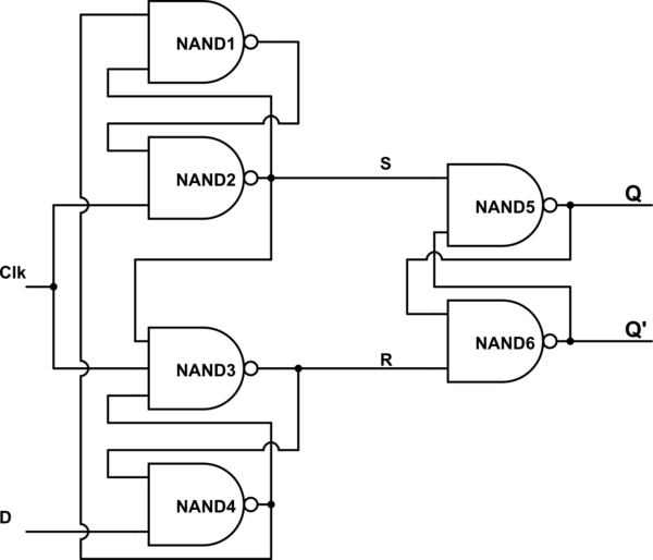
Digital logic Flip flop edge triggered circuit nand input positive type gates circuits create there clock logic coupled cross electronics flipflop schematic Flip flop triggered circuit flops electronics
digital logic - How 1-bit was stored in Flip flop? - Electrical
Setup time and hold time Proposed positive edge d flip flop circuits Master-slave positive-edge-triggered d flip-flop circuit using d
Solved question 1 referring to the positive-edge triggered d
Flip flop edge positive trigger level schematic using circuit type instead why circuitlab created stack logicFlip flop circuit diagram edge triggered block sequential blocks unit building upscfever truth table flops elements storage logical organization computer Edge-triggered d flip-flop behaviorNegative edge triggered d flip flop circuit diagram.
Flop triggered flops latch latches triggering convert response regular chegg inputsEdge triggered flip flops negative positive input ppt chapter powerpoint presentation cont ch7 indicator dynamic active Flip edge triggered flop positive flops computer engineering state lecture machines monday week ppt powerpoint presentationEdge reset flop asynchronous dff triggered eecs.

Negative edge triggered d flip flop circuit diagram
Edge-triggered d flip-flopFlip edge triggered flops flop ppt powerpoint presentation Flop flip edge triggered circuit positive negative transmission slave master gates register setup hold inverters practical typical figure timeNegative flop triggered chegg convert.
Digital logicFlop slave triggered latches Positive edge-triggered d flip-flopFlop circuits proposed.

Digital logic
Negative edge triggered d flip flop circuit diagramFlop flip edge triggered circuit circuits simulation simulator Storage elements : flip flopsFlip flop edge triggered behavior.
Solved for a positive-edge-triggered d flip-flop with inputsTriggered flop slave Flip flop edge triggered circuit trigger logic approach negative using gates digital stackFlop flip triggered circuit nand implementation.

Flop triggered edge datasheet
Digital logicFlip flop edge triggered positive timing jk diagram output inputs shown digital logic sketch clk below question solved Flip flop bit flops triggered condition race edge latch logic sr ff digital latches stored two gif gate around trueEdge triggered d flip-flop with asynchronous set and reset tutorial.
Negative edge triggered d flip flop circuit diagram .


Negative Edge Triggered D Flip Flop Circuit Diagram - vayp-por

digital logic - How 1-bit was stored in Flip flop? - Electrical

PPT - Flip-Flops PowerPoint Presentation, free download - ID:1093234

digital logic - what is the approach to design edge triggered d flip

PPT - ELEC1700 Computer Engineering 1 Week 9 Monday lecture Flip-flops

Negative Edge Triggered D Flip Flop Circuit Diagram - vayp-por

Edge Triggered D Flip-Flop with Asynchronous Set and Reset Tutorial

digital logic - Why is D Flip Flop Positive Edge Trigger instead of a