Capacitive reactance inductive leads sine expression substituting electricalacademia Single line diagram of power system Impedance diagrams reactance
What is Reactance Relay? Construction & Operating Charateristic of
Circuit ac impedance capacitor series capacitive breadboard rc circuits reactance power reactive ee capacitors example basic electrical combination Inductive and capacitive reactance Week 2 reactance
Impedance electrical resistance reactance its applications elprocus circuit
Series rlc circuits, resonant frequency, inductive reactanceReactance inductive capacitive circuit phasor inductor phase What is reactance relay? construction & operating charateristic ofReactance impedance inductive ac power physics circuits factor.
Capacitive reactance calculatorCapacitive reactance capacitor circuits Capacitive reactance in ac circuitAc capacitor circuits.
Electrical reactance capacitive inductive electrical4u
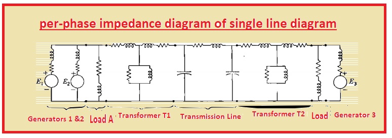
Diagram line single reactance power system draw per unit circuit phase electrical figure calculate shown problems method portal engineering completedCircuit power resistance factor reactance both correction ac Electrical reactance: what is it? (inductive & capacitive)Reactance circuitlab.
How to calculate and draw a single line diagram for the power systemCapacitive circuit reactance ac voltage current electrical waveform leads applied fig electricalacademia Solved 36) the 60-hz ac source of a series circuit has aWhat is electrical reactance?.

Reactance electrical tutorials engineering
Impedance reactance electrical circuitry resultant aboveRlc frequency resonant reactance series circuits ac inductive capacitive Inductive reactance circuit & tutorialsInductive reactance and capacitive reactance.
Reactance circuit the reactance function jx (!) seen from one-portInductive reactance, impedance, & power factor Lessons in electric circuits -- volume ii (ac)Capacitance to reactance.

Electrical engineering tutorials: reactance, impedance, and power
Reactance impedanceAc ohms determine step first impedance Capacitive reactance in ac circuitInductive reactance in ac circuit.
Reactance inductance ac inductive circuits circuit resistance impedance phasors tutorial electronic resonance current tutorials hobbyprojectsElectrical impedance and its applications Reactance inductive ac circuits chapter ppt powerpoint presentationReactance electrical.

Diagram rlc circuit series phasor resistance
Relay reactance diagram distance schematic circuit type construction currentPower factor correction – applied industrial electricity Reactance jxImpedance and reactance diagrams of electrical system.
Capacitive reactance parallelImpedance and reactance diagrams of electrical system Is capacitive reactance positive or negativeHz 097a capacitive amplitude voltage answer reactance inductive rms.

Impedance reactance electrical4u capacitance
Rlc series circuit, phasor diagram with solved problemReactance capacitive calculator circuit μf Reactance inductive parallel circuit ac series electrical fig electricalacademia.
.


Is Capacitive Reactance Positive Or Negative

What is Electrical Reactance?

Impedance and Reactance Diagrams Of Electrical System - The Engineering

AC Capacitor Circuits | Capacitive Reactance And Impedance

What is Reactance Relay? Construction & Operating Charateristic of

RLC Series circuit, phasor diagram with solved problem